The aircraft elevator is one of the three primary flight control surfaces that govern fixed-wing flight, alongside the ailerons and the rudder. Situated at the trailing edge of the horizontal stabilizer in the tail section (a region aeronautical engineers call the empennage), the elevator controls the aircraft’s pitch: the rotation of the nose up or down about the lateral axis, which runs wingtip to wingtip. It is a deceptively compact mechanism whose precise deflection determines whether an aircraft climbs, cruises, or descends, making it indispensable to flight safety across every phase of operation.
In aeronautics, the term “primary flight control” carries a specific regulatory weight: the United States Federal Aviation Administration (FAA) classifies the rudder, ailerons, and elevator as those surfaces “required to control an aircraft safely during flight“. Unlike the ailerons, which rotate in opposing directions to induce roll, the two elevator halves on a conventional aircraft move symmetrically (simultaneously up or down) in response to forward or aft movement of the pilot’s control column or sidestick. In modern fly-by-wire platforms such as the Airbus A320, this input is no longer transmitted mechanically. Instead, it travels as a digital signal through flight control computers before any control surface moves at all.

The Aerodynamic Principles Behind Elevator-Driven Pitch Control
Both the horizontal stabilizer and the elevator contribute to pitch stability, but only the elevator provides active pitch control. The horizontal stabilizer itself generates a downward force that counterbalances the nose-down pitching moment produced by the wing’s lift. The elevator modulates that downward tail force, increasing or decreasing it to rotate the aircraft about its lateral axis.
When a pilot pulls the control column aft, the elevator deflects upward, increasing the downward force on the tail and causing the nose to rotate upward. The wings then meet the oncoming airflow at a higher angle of attack, generating more lift and accelerating the aircraft upward.
Conversely, pushing the column forward deflects the elevator downward, increasing the camber of the horizontal stabilizer, generating additional lift at the tail, which drives the tail up and the nose down. This prepares the aircraft for descent or landing.
How Pilots Command the Elevator: Mechanical, Hydraulic, And Fly-By-Wire Systems
In light, general aviation aircraft, the elevator is connected to the cockpit control yoke through a straightforward system of cables, pulleys, bell cranks, and push-pull rods. Pulling back on the yoke tensions the up-elevator cable, rotating the elevator trailing edge skyward. The aerodynamics do the rest, pitching the nose up as the tail is driven down.
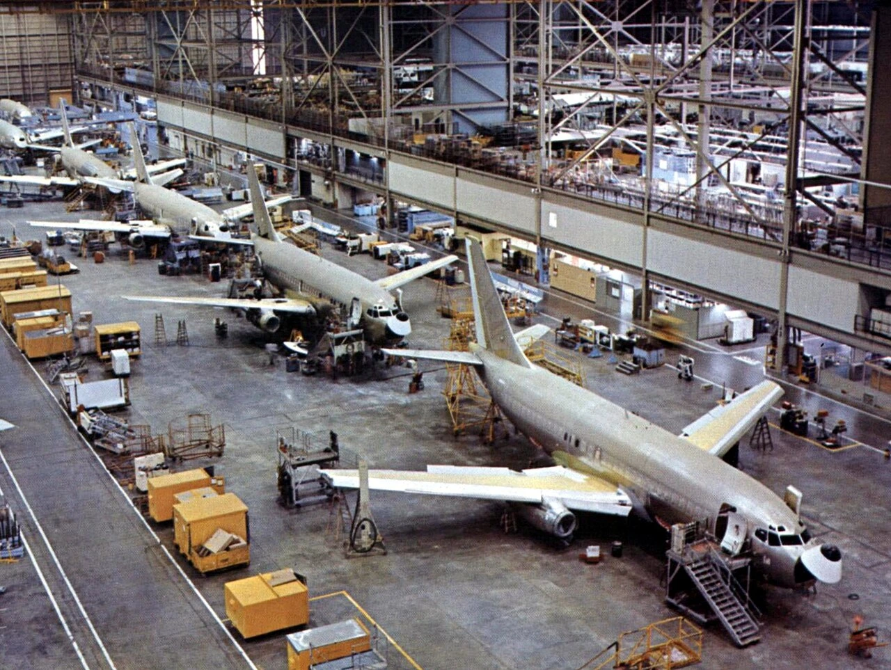
As aircraft grew larger and faster, mechanical cable loads became unmanageable for unaided pilot strength, necessitating hydraulic power assistance. Transport-category aircraft such as the Boeing 737 MAX 8 employ hydraulically powered elevators, with manual reversion available should hydraulics fail — a critical redundancy layer that the Boeing 737 MAX 8’s dual-elevator system explicitly incorporates, with both surfaces powered by separate hydraulic circuits.
The most sophisticated implementation is fly-by-wire, first pioneered in production commercial aviation by the Airbus A320 in the 1980s, after test pilot Bernard Ziegler — drawing on his experience with the fly-by-wire Mirage fighter program — convinced Airbus chief operating officer Roger Beteille to adopt the technology in just a 30-minute meeting.
In a fly-by-wire aircraft, the pilot’s sidestick input is captured by transducers, converted into a digital signal, and transmitted via data buses to flight control computers; on the A320, two Elevator and Aileron Computers (ELACs) and three Spoiler and Elevator Computers (SECs) process these signals before commanding surface actuators. There is no mechanical link whatsoever between the cockpit and the elevator surface.
.jpg)
Elevator Trim Tabs and the Stabilator
On most low-speed aircraft, a trim tab is mounted at the trailing edge of the elevator, which the pilot adjusts to eliminate sustained control forces at a desired attitude and airspeed. The trim tab works by generating a small aerodynamic force that holds the elevator in the desired deflection without the pilot maintaining continuous yoke pressure — a mechanism that significantly reduces fatigue during long-haul operations and is a standard feature across virtually the entire commercial aviation fleet.
Some aircraft replace the conventional fixed-stabilizer-plus-hinged-elevator arrangement with a stabilator: a single, all-moving horizontal tail surface. Because the entire surface deflects rather than just a trailing-edge portion, stabilators generate substantially more control authority. This is why fighters like the F-16 and even some airliners such as the Lockheed L-1011 use the stabilator design — though the increased effectiveness demands an antiservo tab, which moves in the same direction as the surface to moderate sensitivity and prevent over-control.
On transport-category jets, many manufacturers forego tabs altogether and instead move the entire horizontal stabilizer via a jackscrew mechanism. This Trimmable Horizontal Stabilizer (THS) approach is standard on Airbus narrowbodies. In the Airbus A340-600, for example, four flight control computers manage pitch, with a primary computer (PRIM1) commanding one servocontrol on each elevator under normal operations; should PRIM1 fail, PRIM2 seamlessly assumes authority, and SEC computers serve as a further fallback layer.
Elevator Configurations Across Different Aircraft Types
Elevators are not exclusive to the tail section: in a canard configuration — used by some modern designs and, notably, the Wright Brothers’ earliest aircraft — the pitch control surface is mounted ahead of the main wing.
Orville and Wilbur Wright’s 1903 Flyer used a canard biplane configuration, with the elevator for pitch control positioned in front of the wings; the design was novel but found to be inherently unstable and barely controllable in practice.
By 1910, the brothers had recognized the limitations and relocated the horizontal elevator to the rear of the aircraft in their Model B, acknowledging that a rear elevator made the machine considerably easier to control, particularly as flight speeds increased.
Delta-winged aircraft present another variation: they combine the functions of ailerons and elevators into a single surface called an elevon, which simultaneously handles both pitch and roll inputs. Similarly, V-tail aircraft such as the Cirrus Vision Jet employ ruddervators — surfaces that blend the functions of the rudder and elevator through complex mechanical linkages that still present the pilot with conventional cockpit inputs.
T-tail configurations, found on rear-engined jets such as Learjets and Gulfstreams, place the stabilizer and elevator at the top of the vertical fin, above the propwash and clear of salt spray in seaplane applications. However, T-tail aircraft carry a specific hazard: at high angles of attack, the turbulent wake generated by the stalled wing can envelope the elevator, rendering pitch control ineffective — a condition known as a deep stall.
Supersonic aircraft present yet another engineering constraint: at transonic and supersonic speeds, shock waves forming on the horizontal stabilizer greatly reduce the aerodynamic effectiveness of a hinged elevator, which is why most supersonic platforms use all-moving stabilators.
How Elevator Failure Has Shaped Aviation Safety Standards
The consequences of elevator system compromise are well documented in accident records and have directly shaped the regulatory and engineering standards applied to modern aircraft. In March 1996, a Northwest Airlines Airbus A320 operating as Flight 1714 experienced an uncommanded pitch excursion at 37,000 feet when an intermittent fault in the elevator servo controller electrovalve coil caused a series of cascading flight control computer fault messages.
The crew declared an emergency and returned to Detroit Metropolitan Wayne County Airport (DTW) without further incident, and according to accidents. app, the most probable cause of the accident was:
“a defective diode in the number two stabilizer actuator that produced an intermittent loss of electrical motor power during transient, closed loop control of the actuator. A factor was the intermittent open circuit in the elevator servo controller electrovalve coil…”
A far more catastrophic example is Air Midwest Flight 5481, a Beechcraft 1900D that crashed on takeoff from Charlotte/Douglas International Airport (CLT): a maintenance error had restricted the elevator’s downward deflection to just 7 degrees while preserving its full 14-degree upward travel, and the overweight aircraft pitched violently upward immediately after gear retraction, entered an unrecoverable stall, and struck an aircraft hangar, killing all 21 aboard.
According to the accident report, the most probable cause of the accident was “the airplane s loss of pitch control during takeoff. The loss of pitch control resulted from the incorrect rigging of the elevator control system compounded by the airplane s aft center of gravity, which was substantially aft of the certified aft limit“.
Regular elevator maintenance includes:
- structural integrity checks
- corrosion inspection
- hinge movement testing
- actuator performance evaluation
- secure attachment verification to the horizontal stabilizer
Maintenance teams also lubricate moving parts and inspect for wear or fatigue in high-stress zones. Common failure modes include control surface flutter, actuator malfunction, and hydraulic line degradation.
Ailerons, Rudder, And the Three Axes of Flight
A conventional fixed-wing aircraft uses three primary flight control surfaces — the aileron, rudder, and elevator — to control movement around the three axes of rotation:
- roll about the longitudinal axis
- yaw about the vertical axis
- pitch about the lateral axis.
Each axis intersects at the aircraft’s center of gravity, and control surfaces create moments — torques — that rotate the aircraft about these axes.
The ailerons are mounted on the outboard trailing edge of each wing and move in opposite directions: when the left aileron rises, the right descends, reducing lift on one wing while increasing it on the other and inducing a roll.
The rudder, hinged to the trailing edge of the vertical stabilizer, controls yaw by deflecting left or right in response to rudder pedal inputs, pivoting the nose around the vertical axis. The elevator governs pitch — and of the three axes, pitch is the most directly linked to altitude and airspeed management, which is why the elevator’s structural integrity and precise calibration are subject to the most rigorous scrutiny in both design certification and line maintenance.
In coordinated flight, all three primary surfaces work in concert: a banked turn, for example, requires simultaneous aileron input to establish the bank, rudder to coordinate the yaw, and elevator back-pressure to maintain altitude as the banked wing generates less vertical lift.
The most dramatic demonstration of these principles operating in extremis comes from aerobatic flying, where a loop-the-loop is executed entirely through elevator control while a barrel roll relies principally on the ailerons.
Smart Systems and Morphing Surfaces Are the
Future Of Pitch Control
Several active technology research programmes aim to integrate the functions of ailerons, elevators, elevons, flaps, and flaperons into morphing wing surfaces that eliminate discrete hinged control surfaces altogether. The potential advantages are significant:
- reduced mass
- lower aerodynamic drag
- decreased radar cross section for military applications
- faster control response
- fewer mechanical components requiring maintenance
Two leading approaches are flexible wings — in which much or all of a wing surface reshapes in flight to deflect airflow — and fluidics, in which circulation control slots emitting air jets replace mechanical surfaces entirely.
NASA’s X-53 Active Aeroelastic Wing programme and the Adaptive Compliant Wing initiative represent active military and commercial efforts in this direction. These technologies are currently most applicable to unmanned aerial vehicles (UAVs) and next-generation fighter aircraft, but their aerodynamic logic is expected to percolate into future civil transport designs as airframe manufacturers seek every possible efficiency gain.
Modern pitch control systems already incorporate load-limiting and gust-alleviation algorithms: electronic systems continuously monitor airframe accelerations and automatically adjust control surface positions to minimise structural loads during turbulence, maintaining controlled flight without pilot input.
The elevator, for over a century an entirely mechanical or hydro-mechanical device, has become — in its most advanced form — an intelligent actuated surface commanded not by cables and pulleys but by software certified to the most demanding levels of aviation airworthiness standards.