Picture: Michael32710 | Wikimedia Commons
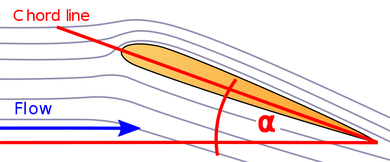
Angle of Attack (AOA) can be defined as, “the angle between the chord of a wing or the reference line in a body and the direction of the undisturbed flow or relative wind in the absence of sideslip”
Picture: Olivier Cleynen | Wikimedia Commons
.svg)
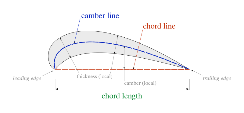
Chord line is an imaginary line which is drawn between the leading edge and trailing edge of an airfoil parallel to the direction of the airflow. On the other hand, relative wind is the direction of airflow with respect to the direction of the wing.
Picture: Olivier Cleynen | Wikimedia Commons
.svg)
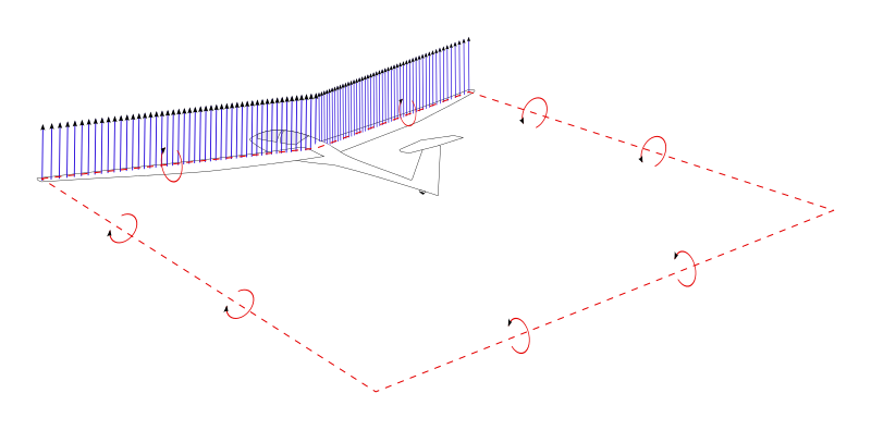
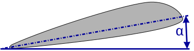
Angle of Attack is the primary reason for occurrence of lift. Without an effective angle of attack, lift cannot be created. However, lift can be created when the angle of attack is zero depending on the shape of the airfoil. Until the stall point, lift increases along with angle of attack.
Picture: Theresa knott | Wikimedia Commons
.svg)
Unlike angle of attack, angle of incidence is the constant angle between the chord line of an aircraft wing and the roll axis. Angle of incidence cannot be changed under normal conditions as it is fixed during manufacturing.
Picture: James Darcy | Wikimedia Commons
_approaches_the_ground_at_a_24_degree_angle.jpg)
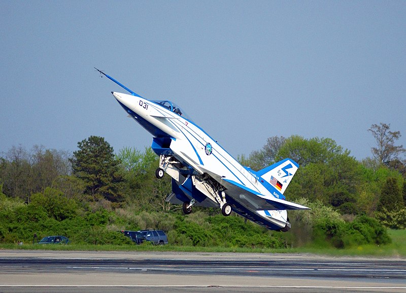
The aircraft increases its angle of attack during take-off in order to generate sufficient lift. Then the angle of attack is lowered for an efficient flight. The angle of attack is increased during landing as well.
Picture: JCV127 | Wikimedia Commons
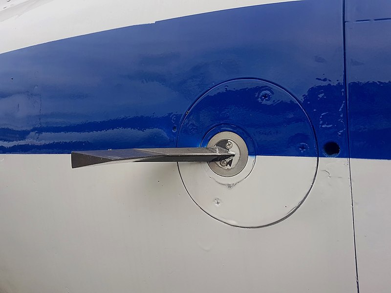
An angle of attack sensor is a device used to measure the angle of attack of an aircraft. Real time data is sent to pilots which helps to prevent stalls and improve the safety of the flight.
Picture: Phoenix7777 | Wikimedia Commons
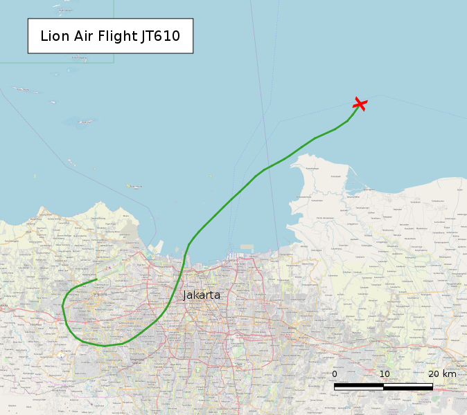
The accident of Lion Air Flight 610 in 2018 was caused due to miscalibration of angle of attack sensor. This occurred due to improper maintenance. There were 189 fatalities due to this accident. Similarly, the accident of Ethiopian Airlines Flight 302 also occurred due to the angle of attack sensor sending wrong readings.

Picture: NASA/MSFC | Wikimedia Commons
_in_a_video_by_NASA-MSFC_02.jpg)
In order to prevent accidents caused by angle of attack sensor failures, improved and advanced sensors should be used, use of enhanced stall warning systems, improved flight data monitoring, pilot training to understand how sensors work, and regular maintenance of sensors should be done.
Picture: NASA | Wikimedia Commons
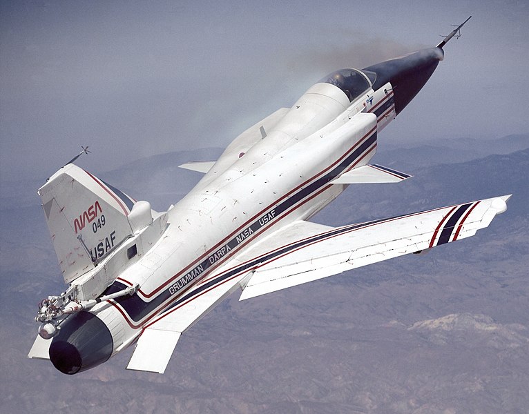
The critical angle of attack is the maximum angle at which an aircraft can maintain controlled flight without any stall. When the critical angle of attack is exceeded, the aircraft enters a stall condition which if it is not corrected, it may result in loss of control.

.jpg)
When the angle of attack is too low, the aircraft wings will generate less lift. This will unable the aircraft to gain enough altitude and will be difficult to maintain lift during flight.